Jaw Style Coupling Selection Process
The assortment method for figuring out the appropriate jaw coupling size and elastomer needs working with the charts proven within the following pages. You can find three components for being selected, two hubs and one elastomer. Once the shaft size on the driver and driven from the application are in the similar diameter, the hubs chosen is going to be the identical. When shaft diameters vary, hubs picked will differ accordingly.
Data necessary in advance of a coupling is usually selected:
HP (or KW) and RPM or Torque of driver
Shaft sizes of driver and driven gear and corresponding keyways
Application description
Environmental ailments (i.e. extreme temperature, corrosive disorders, space limitations)
Methods In Picking A Jaw Coupling
Phase 1: Establish the Nominal Torque of your application by using the following formula:
Nominal Torque = in-lb = (HP x 63025)/RPM
Nm = (KW x 9550)/RPM
Step two: Applying the Application Support Things Chart one choose the services issue which very best corresponds to your application.
Stage three: Determine the Style and design Torque of the application by multiplying the Nominal Torque calculated in Step one from the Application Service Issue established in Step two.
Style and design Torque = Nominal Torque x Application Service Factor
Phase four: Making use of the Spider Efficiency Information Chart 2, select the elastomer material which most effective corresponds to your application.
Phase 5: Working with the Jaw Nominal Rated Torque Chart 3 , find the ideal elastomer materials column for the elastomer picked in Step four.
Scan down this column to the initial entry where the Torque Value from the appropriate column is greater than or equal to the Style Torque calculated in Phase three.
As soon as this value is found, refer to the corresponding coupling size while in the very first column of the Jaw Nominal Rated Torque Chart three .
Refer to your greatest RPM worth for this elastomer torque capability to be sure the application prerequisites are met. When the necessity will not be satisfied at this time, a further style of coupling might be demanded for your application. Please seek the advice of Lovejoy engineering for assistance.
Phase 6: Compare the application driver/driven shaft sizes to your maximum bore size out there over the coupling picked. If coupling bore 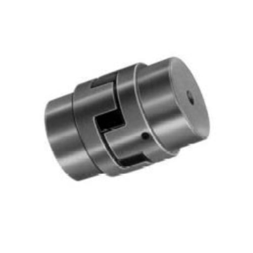 dimension isn’t huge adequate for the shaft diameter, pick the next biggest coupling that should accommodate the driver/driven shaft diameters.
Step 7: Applying the UPC variety selection table , find the proper Bore and Keyway sizes needed and locate the amount.
Jaw Coupling Selection Process
Tags: